Guide to Understanding Floor Plans & Blueprints
Now that your house plan blueprints have arrived, what’s next? Blueprints are sets of pages that communicate the different layouts and measurements of your new home, so it’s important to understand how to read them. Having this knowledge allows you to better track the building process along the way and can help you convey any tweaks or questions you have for your builder.
Though you don’t have to fully understand every number and measurement on a blueprint (that’s the home builder’s job!), a decent understanding of the blueprints means you’ll be able to better visualize your new home during each step of construction.
How to Read House Blueprints
Here are some general tips to remember when reading your new home blueprints:
- They are drawn to scale
- Pages are typically in the order of when they’ll be constructed
- The foundation plan shows specifications of the design you selected
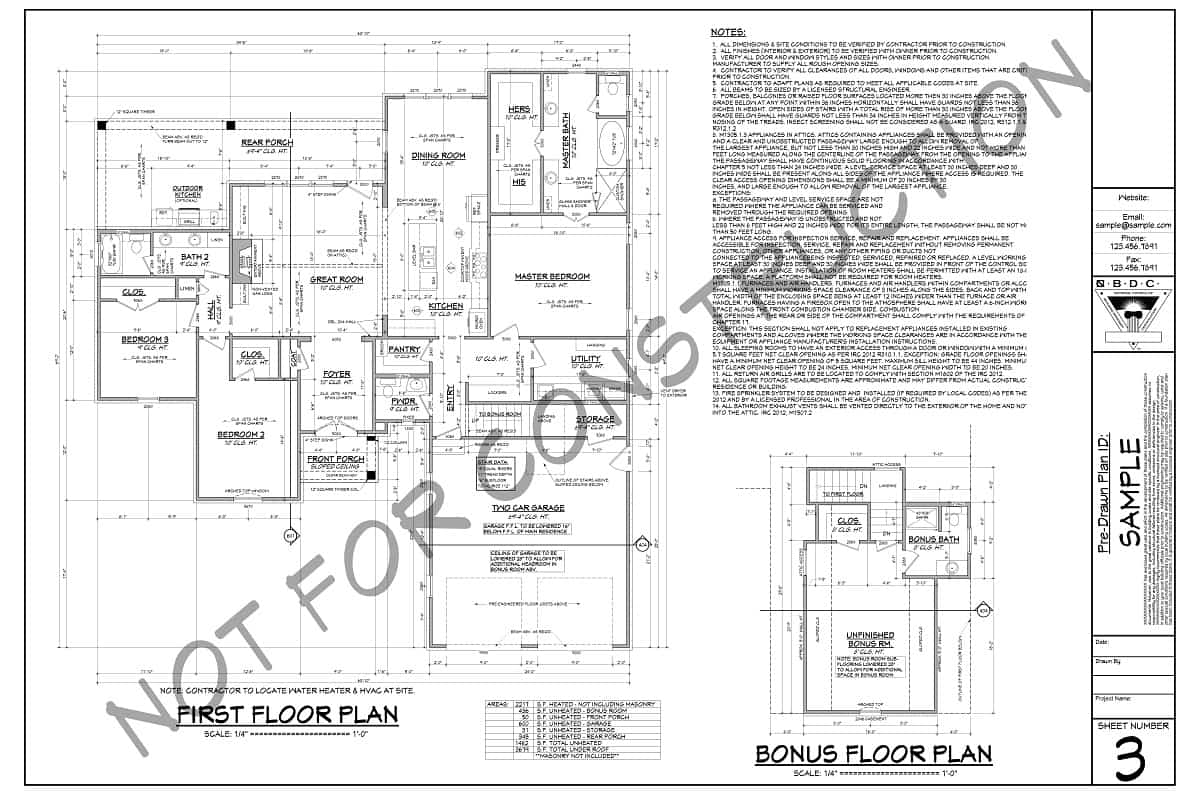
- Floor plans will show details and room dimensions for each floor being built
- Exterior elevations are drawn to scale so necessary measurements can be taken
- Kitchen and bath elevations will help with cabinetry manufacturers
- Miscellaneous details will be included and are plan specific
- Electrical layouts will typically be on their own page
- Framing drawings will outline items like floor joists and trusses
- Locations on plumbing and mechanical systems are usually noted
- Cross sections and details will better explain exactly how the home is being built
We explain each of these in more detail below.
Remember That House Plan Blueprints Are Drawn to Scale
When looking at the print drawings, remember that they are drawn to a scale so that if any specific needed dimension is missing, the contractor can scale the drawing to determine the right measurement. The main floor plans are generally drawn to 1/4" scale, which means that every 1/4" on the plan equals 1' in actual length. Other details, such as framing layouts or built-in details, may be drawn at another scale as 1/8”. The scale of each drawing is usually detailed beneath the drawing or somewhere on the page, usually next to the title.
Reviewing the Different Pages
Each of the different pages in your architectural plan will represent a different piece of the home building process. The pages typically will be ordered by the way the house will be constructed.
Foundation Plan
The foundation plan will depend upon the design selected. Typically, the foundation will be a slab, crawlspace, full basement, or walk-out basement. The basement or foundation plan delineates the location of bearing walls that will support the structure. It also identifies locations of footings, steel (rebar) placement, hurricane strap placement, and other structural elements that are required to support the loads of the upper floors.

How to Read Floor Plans
A floor plan layout on blueprints is basically a bird's eye view of each floor of the completed house. Most floor plans will have a legend to help you read what is included in the drawing. Here are a few common representations you’re likely to encounter in your plans:
You'll see parallel lines that scale at whatever width the walls are required to be. The parallel lines will normally be filled in to appear solid or have a series of angled or wavy lines to indicate the presence of insulation. If there are dark, solid lines for walls, then exterior walls will appear thicker than interior walls, or they may have an extra parallel line on the outside (sometimes shaded in) to indicate siding.
Dimensions may be drawn between the walls to specify room sizes and wall lengths. These plans will help you visualize the entire interior layout of the home from where the master bedroom will be located to the open layout of the kitchen and living room.
Solid lines in a floor plan indicate structures in walls (shelving, fireplace, etc.) and on floors (cabinets, kitchen islands, appliances, sometimes furniture, etc.), and dashed lines in a floor plan usually indicate something three-dimensional that can’t be seen in outline on the floor, such as a vaulted ceiling, tray ceiling, beamed ceiling, or overhead doors in a garage-door opening.
A swing door is typically shown as a straight line perpendicular to the wall, with a curved arc line that connects the line to the wall. The curved line shows how the door swings open, right to left or vice versa, and into which room it opens. Other doors are shown differently:
- Pocket doors: drawn as a dark thin rectangle that inserts into the wall (usually shown partially open)
- Barn doors: shown as a dark thin rectangle that sits in front of the wall (also usually show partially open)
- Folding doors: drawn as a little "V" shape (shown in partially folded position)
- Cased openings in walls (no door) will usually be indicated by dashed lines
Windows (double-hung) are usually shown with three parallel lines in a wall, which is easy to remember: think two walls and pane of glass. Casement windows may be shown with three lines but with the addition of a swing arc line like that used to show doors or with a pair of windows shown partially open.
You'll also see on the floor plan locations of plumbing fixtures like sinks, water heaters, furnaces, etc. Among the walls and dimensions, you will often find notes to specify finishes, construction methods, or even symbols for electrical or to reference cross-sections. You can expect floor plans to be drawn at 1/4” scale.
Exterior Elevations
Elevations are a non-perspective view of the home. These are drawn to scale so that measurements can be taken for any aspect necessary. Plans include front, rear, and both side elevations. The elevations specify ridge heights, the positioning of the final grade of the lot, exterior finishes, roof pitches, and other details that are necessary to give the home its exterior architectural styling. You can expect elevations to be drawn at 1/4” and 1/8” scale.
Kitchen and Bath Elevations
The kitchen and bath elevations show the arrangement and size of each cabinet and any other significant fixtures in the room. These drawings give basic information that can be used to create customized layouts with a cabinet manufacturer.
Miscellaneous Details
These are included for many interior and exterior conditions that require more specific information for their construction. They will be specific to the house plan you purchase and will help the home builders understand the finer details.
Electrical Layout
Electrical layouts are sometimes on a separate page to make reading them a little easier. The layout will show locations of light fixtures, fans, outlets, light switches, etc. There is usually a legend on the page, which explains what each symbol represents. There may be such legends for heating systems, door swings, and sizes, or even to specify certain finishes.
Roof Layout / Framing Drawings
Framing drawings are also drawn to scale and outline the layouts of items such as floor joists and trusses, beam locations and other structural requirements. Framing layouts don't get into the details of each stud location in the walls because framing contractors are required to follow certain rules and regulations to ensure that the home meets the required building code specifications. However, there are often cross sections within the plan pages that outline the general methods of wall construction or floor assembly. A roof layout plan will give you a bird's eye view of the roof which shows the ridges, valleys, and other necessary information.

Plumbing and Mechanical Systems
These systems are generally not covered extensively on the blueprints other than the locations of fixtures and main service lines. If you are going to the expense of more complicated heating systems, such as in-floor radiant heat or even an engineered forced-air system, these drawings need to be completed by a heating or plumbing specialist.
Cross Sections and Details
Overhead views or floor plan views of the structure don't always provide enough information as to how the home is to be built. Often, cross sections or details will explain certain special conditions more appropriately. A cross section is basically a view of the home as if it were sliced down the center. This allows you to view the home from the side and understand a little better the relationships of varying floor heights, rafter lengths, and other structural elements.
These are the basics to reading house plan blueprints. Keep in mind, however, that what is included in plans will vary according to the designer who drew them.
Understand the Steps Involved in House Construction
Now that you know how to read your plan, you must understand the key chronological steps behind turning a blueprint into a house. Blueprints are the way the designer communicates with the builder to construct a house.
In general:
- The land needs to be cleared.

- The house foundation needs to be dug consistent with the location on the site plan of your building lot.
- Concrete needs to be poured.
- Framing needs to be laid to attach the wood frames of your house to the foundation.
- The first floor needs to be framed and plywood sheathing attached.
- First-floor walls need to be constructed with openings framed for windows.
- The next floor, if needed, is then constructed.
- The roof then needs to be framed and plywood sheathing attached.
- The exterior materials and windows need to be applied.
- The electrical wiring, plumbing, and ductwork are placed in walls.
- The heating and cooling systems are installed.
- Then the cabinets, fixtures, and interior appointments are installed.
- Also, there is the work to tie water, electrical, and sewer to your house.
Knowing these steps along with understanding your floor plan blueprints will make it much easier for you to track and visualize your new house during the building process. For some homes, there are even 3D floor plans or video walkthroughs available to help take your visualization to the next level!
House plans are a very important part of the homebuilding process. It is crucial to purchase a plan drawn by a home design professional because he or she has a thorough understanding of how homes are built. If there were any terms on this page that you did not understand – or you would like a more thorough description of their meaning – please visit our construction terms glossary.